I present these ideas as unproven and unfinished ideas.
I've got a lot of stuff coming up and won't have the time to test this out fully, but I wanted to jot everything down and hopefully inspire others to try before I have a chance.
Also, I have only tried this out with a Ditto. I have a Hall of Fame mini on the way and hopefully can test it out on that. I am suspecting that the construction and board layout is similar.
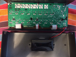
After removing the 4 security screws under the rubber feet, you can take the bottom off. You'll then need to remove the nuts from the 1/4" jacks and the knob to fully take apart the pedal. After you do that, you will have 2 PCBs that connect via a 14-pin header as shown below.
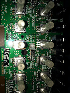
To add CV control over the knob, unsolder the pot. As shown in the picture above, the pads are for the 3.3V, wiper, and ground.
You can replace the pot with something like the following circuit.
Using the switch in the jack, we can set the input to the default 3.3V. The pot acts in the same way as the pot on the device originally acted. The resistor and the zener limit the voltage to 3.3V so a CV of 10V with the potentiometer set to maximum would get cut down to 3.3V and nothing will get fried. In this case, the potentiometer acts as an attenuator for the CV.
On the underside of the PCB, we have the pads for the LED. I recommend removing the LED and replacing it with one on your panel panel so you can see what is going on.
Another consideration is the USB jack. It would be great to have this accessible for any of the TonePrint capable effects so you can tweak the effect parameters with your computer or iOS device. My recommendation for this is to take a mini USB cable and cut it. Then get a female USB B jack that is panel mountable like the one below. Wire up the mini USB cable to the jack with the shortest wiring possible while preserving as much of the shielding as possible.
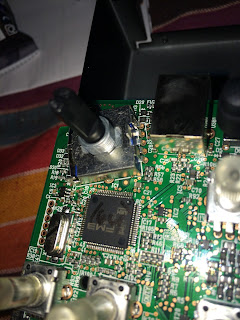
The back of the bottom board has the majority of the important connections.
Starting off with power, we need to supply the boards with 9VDC. TC's website and manual says they require 9VDC at 100mA. I haven't risked giving them 12VDC to see if they still survive, but let's assume they don't. You'll need to knock the 12V down to 9V. Something like the snippet below will do for filtering the power from Euro and knocking the +12V rail down to 9V. I am sure you can find a better way to do it. I'd remove the barrel jack so you can fit everything in a bit better.
Remove the audio jacks. The 'switches' on them will prevent audio from passing without a cable plugged in. Wire up your 3.5mm jacks to the pins in the picture above. In to the in jack, out to the out, and the grounds.
The signals will have to be attenuated to work with synth levels. To do this, I'd use Ken Stone's Stomp Box Adaptor circuit. I'd replace the voltage divider on the input with a potentiometer so you can adjust the input level if desirable.
Next is the switch to enable/disable the effect, or in terms of the Ditto, record/play/ect. To deal with this, I recommend a Maxim DG418 analog switch. It is, essentially a SPST switch in chip form. The IN pin takes in the gate signal that engages the switch when the pin is driven high. I recommend also adding a momentary pushbutton in parallel so you can operate the switch manually when you don't want to use a gate. This is beneficial in the case of the Ditto where you'd want to manually control the deletion of the loop recorded.
The biggest reason I haven't fully pursued this is my weakness for my mechanical design. How should the PCBs be mounted to fit on a Eurorack module?












.jpg)
.jpg)
.jpg)
.jpg)
.jpg)
.jpg)
.jpg)
.jpg)